 |
|---|
|
|---|
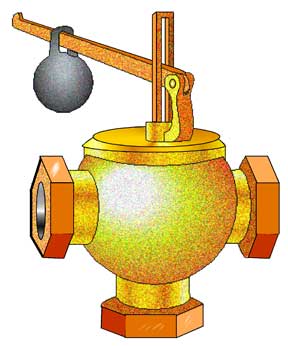 |
Lever Safety Valve This valve looks strange to modern engineers but at one time the lever safety valve was common on steam ships and stationary boilers especially in the U.S. The lower end of the body is connected to the boiler. While the external material was often brass a gun-metal casing was inside. The casing is bored to form a seat for a valve. The valve is guided by a boss underneath it. The valve stem passes through a bushing in the cover. This forms a double stem so the valve can not jam. The valve stem comes in contact with the lever above. The lever is pivoted at one end. A weight on the lever is set at a distance from the pivot point so the fulcrum is sufficient to overcome the pressure in the boiler. This distance was worked out by a formula relating to the pressure and the size of the opening. On a marine boiler the weight was bolted on where a stationary boiler might have a loose weight. When the pressure in the boiler increased enough it would overcome the resistance of the weight and lift the valve. The amount of lift did not need to be large. When boiler pressure was reduced the weight would seat the valve again. There were several disadvantages to this type of safety valve at sea. The valve could open and close due to varying pressures as the ship rolled. The valve was easy to tamper with during a race. This caused more than one explosion. The valve was replaced by spring valves except in vessels engaged in rivers or sheltered bays. |
| Lever type valve | |
 |
|
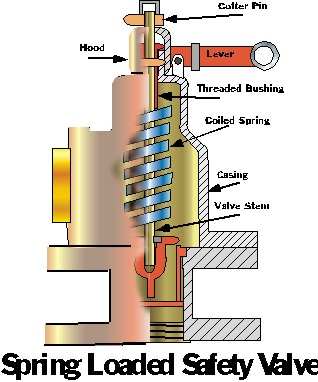
| Book on steam | Newer type spring valve. |
All illustrations and text are the property of R. Sheret and Western Isles Photographics.
Home -Shop - Books - History - Marine Photos