 |
|---|
|
|---|
 |
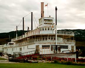
Horizontal High Pressure Engine Stern-wheel types. One of the first economically viable uses for marine steam engines was on the inlets and rivers. Most early steam engines were very low pressure relying on heavy condensers to create a vacuum. When steam boats were introduced to the Mississippi River a higher powered lighter engine was needed. While most of these vessels were side wheelers the same type engine was used. The high pressure engine was used along with a flue boiler until the end of the steam boat era. Most of the Mississippi or western rivers used poppet valves operated by levers and cams. When stern-wheelers came to the west coast faster acting slide valves engines were used. The engines and hull types were first developed on the Columbia River. On the Yukon the Western rivers engines and boats were used below Dawson City. The west coast type slide valve engines were used all over the river. Both engines exhausted to the air. The west coast engine usually exhausted through the stack. While a side-wheel could operate with one engine stern-wheelers always had one engine mounted on each side of the vessel. The engines located aft were balanced by the boiler or boilers forward. |
When the lever is lifted by the wipers steam enters the cylinder. On the other side and other end of the cylinder the exhaust lever is lifted by a wiper. Right: A lever engine on the Belle of Louisville. She operates out of Louisville Kentucky. If you take a trip on her you can see these wonderful engines operating. |
 |
 |
Lever engines Space will not allow an in depth description of the operation of either
engine. The lever engine evolved into its present form by the 1830 -1840s.
The pressure had increased to 100 psi. Soon there were variations of the
two basic types, fixed cutoff and variable cutoff. |
| Fixed cutoff engine | |
 |
Often two cams on the stern wheel were used, a full stroke
cam for getting away or whenever maximum power was needed. The other, cut-off
or short stroke, cam was used when the vessel was steaming normally. If
the full stroke cam was used the steam valve was open for the full length
of the stroke as was the exhaust valve at the other end of the cylinder.
When the short stroke cam is used the steam valve is open for the first
part of the stroke. The rest of the stroke power is supplied by the expansion
of steam. The cam is encased in a cast iron frame. The frame slides in bearings
and is connected to the cam rod that works the valve gear. Other engines used a variable cut-off system such as the California cut-off. The valve gear for variable cutoff engines was much more complicated than the fixed cutoff engines. They often had three cams. There were some two valve engines as well. |
|
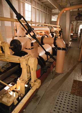
The piston rod moves a crosshead. The pitman arm is connected to the crank. Cam rods connected to the cam operate the valve gear. |
 |
|
| Rees variable cutoff engine. These engines were used in many parts of the world. | |
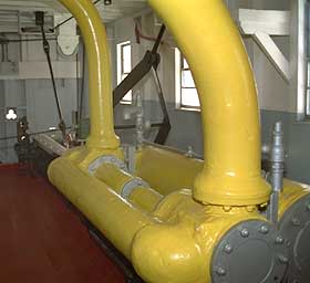  |
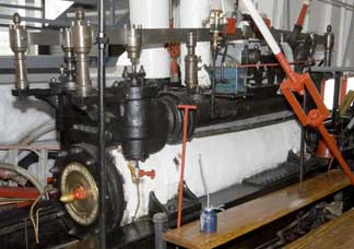
The Slide Valve Engine. Port engine on the Samson V. and a crank and eccentrics on a Yukon stern wheel. The wheel has 3 eccentrics so it probably worked with a compound engine that had a cut off valve. The simpler engine on the Samson V had 1 eccentric for each on the wheel. |
 Klondike 3 in Whitehorse Yukon. Now exhibit.
 |
|
 |
Compound engine Klondike 3. She has a cutoff valve and a method of controlling the valves unlike simpler systems often seen on the west coast. |
| . | |
| Slide Valve Engines The valve theory is similar to a vertical engine except due to length of the cylinder there is a set of valves at each end of the cylinder. The valves were usually a piston type. The valves were operated by eccentrics on the paddle shaft. If cut-off valves were used another eccentric was used. Some compound engines were used on lakes and slower moving rivers. The railroad type boiler was used with a single stack unlike the twin stacks used on the Mississippi boats. The steam from the throttle arrives to the valves through the main steam pipe. When the valve is opened by the eccentric, steam enters the cylinder. As the piston moves downs the cylinder the exhaust valve is opened at the other end. The exhausted steam is sent back to the stack in most cases. Some compound engines had condensers. |
 |
| The engine is a slide valve type but note how the valve gear is similar to the variable cutoff lever engine. | |
| A cut-off valve is sometimes located on top of the main valve.
All valves are controlled by the eccentric and links. The links are shifted
by levers at the controls. The slide valve engines can move from ahead to
astern faster than a lever engine which made them useful on the fast currents
of the west coast rivers. There were many variations of both engines. As stern wheelers were used on lakes and open ocean they needed engines that were powerful but not as fast acting. For more information see Smoke Ash and Steam |
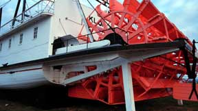 |
| Pitman on stern of Klondike 3. Note rudders located ahead and astern of the wheel. This gave greater control in the river than the older single rudder boats especially when going astern. | |
| Photos, illustrations and story by R. Sheret |
All photos text and images are copyrighted by Western Isles and R. Sheret